ATtiny85 counter tutorial counting events/signals using interrupts
20 May 2025Counters are essential peripheral in microcontrollers since it is used to count external events or internal / external clock pulses. Counters store the number of such events / pulses in registers for retrieval and processing. In ATtiny85 microcontroller, the counter can count up to 256 since its timer module is of 8 bit in size. Counters are generally used in the applications like frequency counters, digital clocks etc.
In this tutorial, we will be configuring the Attiny85 microcontroller as a counter that counts external event triggered by a push button. The counter basically uses the in built Timer peripheral to perform this function. The primary function of timers is to generate time delays. We are going to use Timer0 peripheral for demonstration purpose in this tutorial.
Also Read: ATtiny85 timer tutorial covers generating time using timers delay in detail
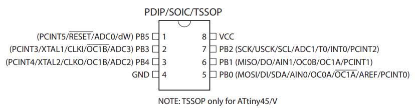
Clock source selection: The counter can be configured to count internal or the external clock pulses. It’s very common to use external clock pulse than internal when comes to counter. In order for Timer/ Counter module to count external events / clock, it should be fed to PB0 pin which has alternative function of T0. The counter can be configured to count either on the positive edge or the negative edge of the clock cycle.
If you are intended to count the clock pulses of the external clock source then the frequency of the clock source must be less than half the system clock frequency (fExtClk < fclk_I/O / 2). Although it is recommended to limit the maximum frequency of external clock source to fclk_I/O / 2.5. Also remember the external clock source cannot be prescaled.
Timer/ Counter 0
There are two timer/counter peripherals in ATtiny85 Timer0/counter 0 and Timer1/counter 1. In this tutorial we are going to use Timer0 and configure it as counter of external events. It is a 8 bit register which means it can count from 0 to 255.
TCCR0A Register
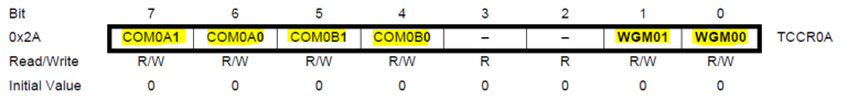
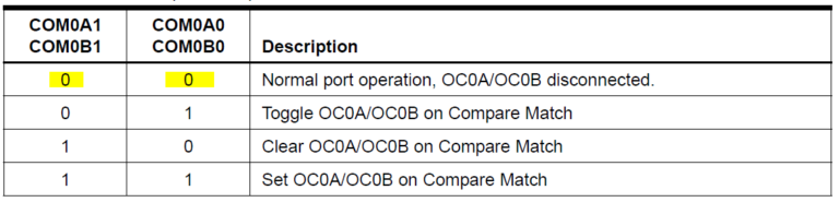
The following bits in TCCR0A register COM0A0, COM0A1, COM0B0, COM0B1 have to be cleared, to operate in the normal port operation. This disables the compare matching feature built within timer.
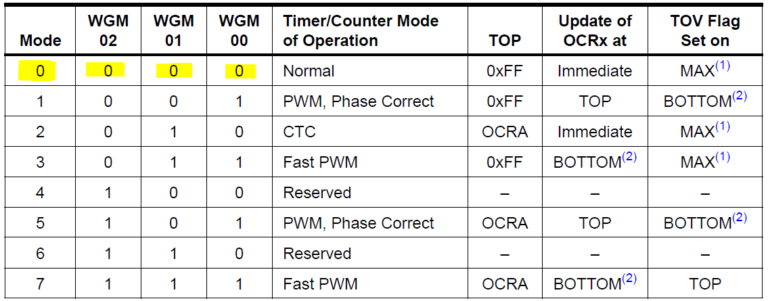
The bits WGM00, WGM01 from TCCR0A and WGM02 from TCCR0B determines mode of operation. Here the operation mode should be in Normal Mode. In this mode, the counting direction is always up that is it increments with each incoming pulse. The timer / counter overflows when the maximum value of 255 is reached. This overflow is marked by raising a oveflow flag which helps to trigger interrupt.
TCCR0B – Clock Source Configuring Register
Attiny85 consists of the 8-bit programmable bi-directional counter. As we are going to use external clock source for counting, we need to configure the bits CS0[2:0] in this register.
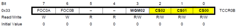
In TCCR0B control register the bits CS00, CS01 and CS02 clock select bits have to be configured.
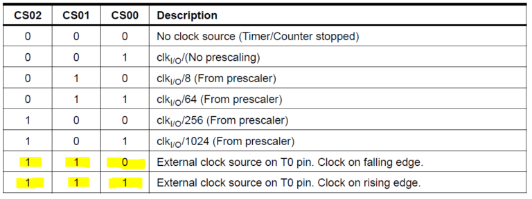
The clock bits have to be set with either 1,1,0 or 1,1,1 respectively, to select the external clock source on T0 with a clock on falling or rising edge accordingly.
TIFR Flag Register
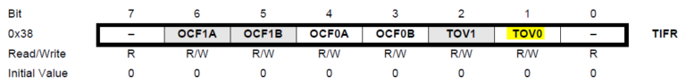
The TOV0 flag bit will be cleared automatically by hardware when interrupt is executed. Alternatively it can cleared manually by writing 1 to it.
TCNT0 Register
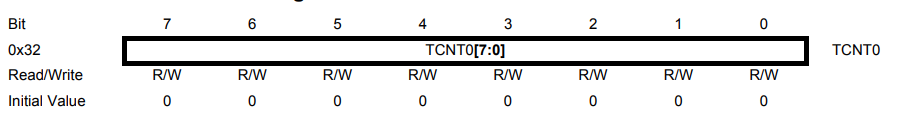
This register stores the count value and the value in this register will be automatically incremented when new clock pulses or event input goes to T0 or PB0 pin.
Circuit to count external events triggered by Push button:

{
DDRB=(1<<PB1)|(1<<PB0);
TCCR0A = 0X00; //TCCR0A to low for normal port operation and mode 0.
TCCR0B = 0X00; //WGM02=0
TCCR0B |= (1<<CS02)|(1<<CS01); //CS02=1, CS01=1 CS00=0 Clock on falling edge
TCNT0 = 0x00; //initializing the counter to 0
}
void counter_reset()
{
TCNT0=0x00; //reset value to 0
i=0;
}
int main()
{
counter_setup();
while(1)
{
i=TCNT0;
if ( i>=10&&i<30) // First 10 counts
{
PORTB |= (1 << PB1); //light up LED in PB1
//reset counts
}
else if(i>=30) //second 20 count
{
PORTB|=(1 << PB0); //light up LED in PB2
counter_reset();
}
}
}
Counting more than 255: We can use interrupts or manual flag check method if you are looking to count more number of events or count incoming signal pulses. Using interrupts will be most effective as handling interrupts will be much more easier than manually checking overflow flag. In this case you can follow the interrupt part of ATtiny85 timer tutorial. It only differs with the choice of clock source selection. Below is the sample code that uses interrupt to keep count of events and it lights up LED in PB1 when the count crosses 1000.
#include<avr/io.h>
#define F_CPU 16500000UL
int i,j;
i=j=0;

void counter_setup()
{
 DDRB=(1<<PB1)|(1<<PB0);
 TCCR0A = 0X00; //TCCR0A to low for normal port operation and mode 0.
 TCCR0B = 0X00; //WGM02=0
 TCCR0B |= (1<<CS02)|(1<<CS01); //CS02=1, CS01=1 CS00=0 Clock on falling edge
 TCNT0 = 0x00; //initializing the counter to 0
 sei(); //enabling global interrupt
 TIMSK|=(1<<TOIE0); //enabling timer0 interrupt
}

ISR (TIMER0_OVF_vect)      //Interrupt vector for Timer0/Counter0
{
 i++;
}

int main()
{
 counter_setup();
 int actual_count;
 while(1)
  {
   j=TCNT0;
   actual_count=j+(i*256);
   if ( actual_count>=1000) // First 10 counts
    {
     PORTB |= (1 << PB1); //light up LED in PB1 if count reaches 1000
    }
  }
}
Try this out: Configure ATtiny85 Timer0 and Timer1 to count and keep track of two external events. Set the maximum limit of event count to 1000.