ATtiny85 timer tutorial generating time delay using Interrupts
20 May 2025Timers are popular peripherals in microcontrollers. These timers are responsible for generating accurate time delays using Microcontroller. Also Timers can be used to work as a counters, PWM generation, Capture external signals and so on. Hence these timers are quite important to understand. This tutorial explains the timer in ATtiny85 microcontroller and how to configure and use them.
Clock source selection: This is the first question that comes to mind when speaking of timers. What clock source does ATtiny85 timers use ? The The timer peripheral can be clocked with internal or external clock source. As per the ATtiny85 datasheet will use its internal RC Oscillator of 8MHz frequency when being shipped. For tutorial purposes we are using ATtiny85 development board from Digistump. In this ATtiny85 is configured to operate at internally generated 16.5MHz clock and we are using this clock source to drive the timer.
Timer0: There are two timer peripherals in ATtiny85 Timer0 and Timer1. In this tutorial we are going to use Timer0 to explain its working. Timer0 is a 8 bit timer which means it can count from 0 to 255. This can be configured to operate as a counter as well. The timer functionality can be further extend using the compare match peripherals which enables the timer to count events, PWM generation and so on.
TCCROA – Timer/Counter Control Register A Configuration of Timer0 register can be done using two registers TCCR0A and TCCR0B
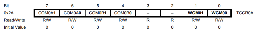
TCCR0A register helps user to configure the Timer to operate in normal mode. This is the mode in which the timer will start the count from 0 and reaches a maximum of 255 which is the highest limit for 8 bit register. In normal operation mode the compare match features and its pin will be disconnected. The below table shows the types of modes that can configured by writing the bits COM0A1, COM0A0, COM0B0, COM0B1.
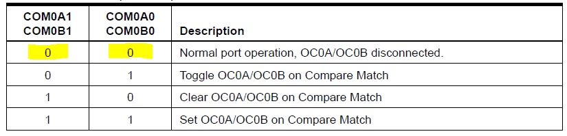
We are going to write 0 to COM0A1, COM0B1, COM0A0, COM0B0 bits to choose the normal port operation here. Next we need to configure the bits WGM02, WGM01, WGM00. The below table shows the values for these bits and respective mode selections.
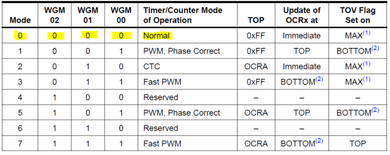
We will configure these bits to operate in Normal mode since we want our timer to count from 0 to TOP value which is 0xFF or 255. Alternatively you have options to configure timer to generate PWM signal and Clear timer on Compare ( will be explained different article ).
TCCR0B:
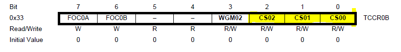
This register is also used to configure the operation of Timer0. Remember the bit WGM02 from the previous table. Note that WGM02 bit is located in TCCR0B register not TCCR0A register. The CS02, CS01, CS00 bits in this register is used to prescale the clock pulse of our timer. Prescaling is used to divide the incoming clock pulse to feed our timer peripheral. This feature will be extremely useful when our microcontroller runs at high speed and we need our timer to run in relatively low speed which will make delay generation more to speed which humans can relate to.
Our microcontroller runs at 16.5MHz which is relatively high speed. The time period of this frequency clock pulse
T = 1 / F = 1/ 16500000
T = 606us
This time period is quite less to create delays that can be perceived by humans. So we need to reduce the clock frequency that is fed to Timer0 peripheral. This can be achieved by using prescaling the input clock frequency.
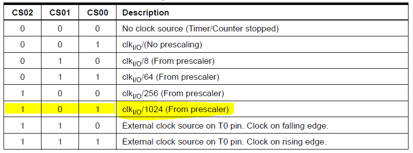
Setting the bits CS00, CS01, CS02 bits to 101 will divide the input clock frequency that is 16.5MHz by 1024. Therefore Timer0 will operate at a clock frequency of 16.11Khz. Now the time period of clock pulse will be
T = 1/ 16.11Khz
= 62us
The time period has been reduced now, this will enable us to generate time delays.
TCNT0 register:
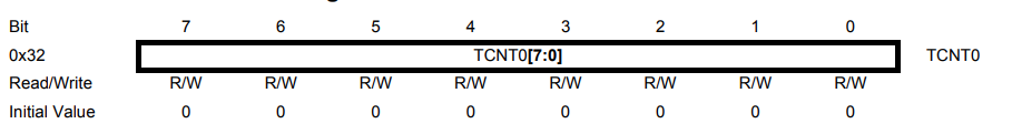
This is a 8 bit data register at which the timer value gets stored. Being a 8 bit register this register can hold values from 0 to 255 after it overflows and start incrementing from 0 again. Upon completion of this count in TCNT0 register timer sets the Overflow flag ( explained below ) as an indication of this event. This overflow can also trigger an interrupt if user has activated this feature.
Time delay calculation: The input clock pulse to Timer0 is prescaled from 16.5MHz to 16.11KHz. This is the speed at which our timer operates now. The time delay generated by Timer0 can be calculated by calculating the time taken for one increment in TCNT0 register and then multiply it to the maximum increments which is 255.
Time taken per increment = 1/16.11KHz = 62us Time taken for 0 to 255 count in TCNT0 register = 62us x 255 = 15.81ms
This implies it takes 15.81ms for Timer0 to increment from 0 to 255 and set the overflow flag or trigger interrupt. Now if we need a delay of 1 sec using Timer then
Number of times timer has to run for 1 sec delay = 1 / 15.81ms = 63.2
Rounding this off, we can conclude our timer need to repeat its overflow operation for 63 times to get a 1 sec time delay. We will use this count to repeat the timer operation in our code to obtain 1 sec time delay.
It’s worth noting that generating time delay using timers can achieve only certain level of accuracy. As per the above calculation repeating the timer loop 63 times will fetch us
Actual time delay = 63 x 15.81 ms = 996.03 ms . This is close to 1000ms which is our 1 second delay. We can generate even more accurate time delay using Compare match in ATtiny85 which is explained here.
Using manual monitoring of Overflow flag: There are two methods we can achieve time delay in ATtiny85. First method is to manually check the Overflow flag after triggering the timer and act when overflow occurs.
TIFR register:
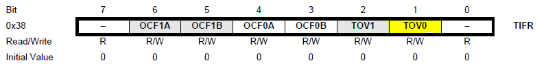
This register holds the bits which indicates the status of Timer0 peripheral. All the bits in this registers are flag bits which will go high when a certain external event occurs. We are interested in the bit TOV0 bit which is the Timer0 overflow flag. This bit will be normally read zero but when the count in TCNT0 register reaches its maximum value that is 255 by default, this bit will be set high by hardware. The programmer needs to read this bit and understand that Timer has reached its maximum value. Upon reading this programmer has to write 1 to this bit to reset this to low state or it will be reset by hardware if enabled interrupt is executed.
In this method the program needs to check the overflow flag and wait for it to go high. It means the code have to be idle in the meantime or there is a good chance the code will miss reading the timer status because upon overflow Timer TCNT0 register will start over again from 0 to 255. This is the disadvantage of using this method.
Steps to configure Timer and use Overflow flag to generate delay: Select the normal mode of operation for timer0 Prescale the internal clock by a factor of 1024 Wait until the TCNT0 reaches the maximum value and flag is raised. Clear the TOV0 flag by writing one to it. Repeat from step 3 for 63 times to achieve a time delay of 1 second. Toggle the LED connected to PB1 pin. Sample code: The below code configures the timer to prescale the input clock by a factor of 1024 and uses overflow flag to read the timer status and repeats the operation to generate time delay and toggle LED connected to its PB1 pin.
#include<avr/io.h>
#define F_CPU 16500000UL
#include<util/delay.h>
void timer_config()
{
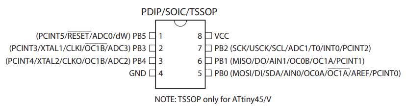
DDRB =0b00000010; // set PB1 as output
TCCR0A=0x00; //Normal mode
TCCR0B=0x00;
TCCR0B |= (1<<CS00)|(1<<CS02); //prescaling with 1024
TCNT0=0;
}
void tmdel()
{
unsigned int i=0;
while(i<=62)
{
while((TIFR & (1 << TOV0) )==0); //Waiting for 0-255 and flag to raise
TIFR|=(1<<TOV0); //Clear the flag
i++; //increment by one
}
}
int main()
{
timer_config();
while(1)
{
PORTB|=(1<<PB1); //PortB1 high
tmdel(); //Delay of 1 second
PORTB&=~(1<<PB1); //PORTB1 low
tmdel();
}
}
Using Interrupt method: This is considered to be the elegant method since it uses the timer interrupt feature of ATtiny85 and doesn’t require code to wait until overflow flag is raised. Here when value in TCNT0 register reaches 255 TOV0 flag will be raised and simultaneously interrupt will be triggered. The program control will be then transferred to Interrupt service routine and there we can use our desired code in the sub routine. In our case we will repeat the timer operation for 63 times to get 1 second time delay.
SREG – AVR status register:
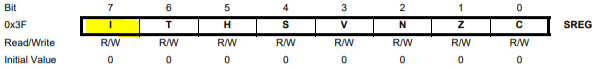
In this register we will use the 7th bit ‘I’ which is Global interrupt enable bit. This bit must be enabled in order to use any interrupt in ATtiny85 controller. Writing one to this enables this bit. Also each of the interrupts will have individual enabling registers and bits which must be used in combination with Global interrupt enable to use interrupts.
TIMSK -Timer/Counter Interrupt Mask Register
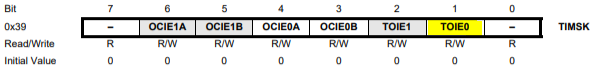
Upon enabling the Global interrupt bit I in SREG we also need to enable Timer0 associated interrupt. This bit is in a special register called as TIMSK register which is responsible for activating and deactivating interrupts associated with Timer0 and Timer1 peripheral in ATtiny85. The bit TOIE0 enables / disables Timer0 interrupts. Writing one to this bit enables the interrupt and zero disables the interrupt.
Do note that overflow flag TOV0 will be set despite using interrupts. But clearing the flag will be taken care by hardware when interrupt in enabled.
Steps to configure Timer and use Interrupt to generate delay: Select the normal mode of operation for timer0 Prescale the internal clock by a factor of 1024 Enable Global interrupt enable I bit in SREG register Enable TOIE0 bit in TIMSK register to enable Timer0 interrupt. Write the Interrupt service routine to repeat the counting operation 63 times to obtain a delay of 1 second. Toggle the LED connected to PB1 pin. Sample code: The below code configures the timer to prescale the input clock by a factor of 1024 and uses interrupts to detect overflow and repeat the operation 63 times to generate time delay and toggle LED connected to its PB1 pin.
#include<avr/io.h>
#include <avr/interrupt.h>
#include<util/delay.h>
#define F_CPU 16500000UL

int intr_count=0;
int sec=0;

ISR (TIMER0_OVF_vect)      //Interrupt vector for Timer0
{
  if (intr_count==63) //waiting for 63 because to get 1 sec delay
  {
    PORTB^=(1<<PB1); //toggling the LED
    intr_count=0; //making intr_count=0 to repeat the count
    ++sec;
  }
  else  intr_count++; //incrementing c upto 63
}

void timer_setup()
{
  DDRB |= (1<<PB1); // set PB1 as output(LED)
  TCCR0A=0x00;   //Normal mode
  TCCR0B=0x00;
  TCCR0B |= (1<<CS00)|(1<<CS02);   //prescaling with 1024
  sei(); //enabling global interrupt
  TCNT0=0;
  TIMSK|=(1<<TOIE0); //enabling timer0 interrupt
  PORTB|=(1<<PB1);
}

int main ()
{
  timer_setup();
  while(1)
  {

  }
}